
 Chengdu GreenWater Co.,Ltd
Home
Library
Media
Venturi Injector Working Principle
Working principle of a Venturi injector: negative-pressure suction, mixing, and diffuser pressure recovery
Starting from the entry of the motive fluid into the nozzle, understand the complete process of velocity increase, static pressure decrease, passive fluid suction, two-phase mixing, and diffuser recovery.
The Venturi injector utilizes pressurized motive fluid to form a high-speed jet through a converging nozzle. The high-speed flow generates a pressure drop, causing gas or liquid to enter from the inlet and mix with the motive fluid; the mixed flow then passes through a diffuser section, where the velocity decreases and the pressure rises, but the outlet pressure remains lower than the inlet pressure.
How Does a Venturi Injector Generate Suction?
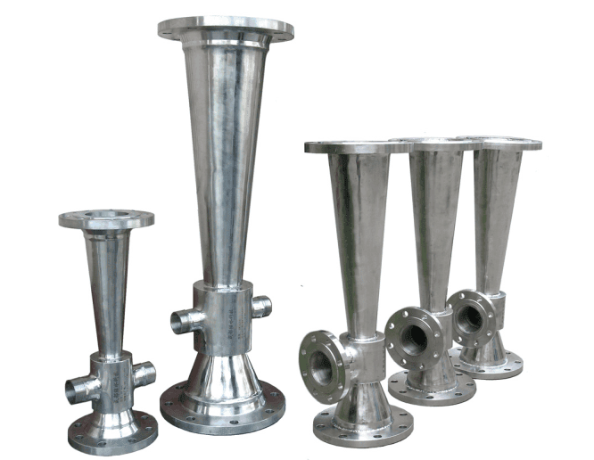
The energy of a Venturi injector comes from pressurized motive fluid. After entering the jet chamber, the motive fluid passes through a constricted nozzle, and the smaller flow cross-section causes the fluid to form a high-speed jet; product documentation describes this process as "pressurized fluid entering the jet chamber to form a high-speed jet fluid."
The high-speed jet creates a pressure drop near the suction port. When the local pressure is lower than the pressure at the gas source or liquid supply end, the substance to be added will enter the Venturi injector from the suction port and merge into the driving fluid. The "suction" mentioned here does not refer to the Venturi injector actively capturing the substance, but rather the pressure difference driving the passive fluid into the low-pressure zone.
P + ½ρv² + ρgz ≈ Constant
When neglecting height changes and simplifying the analysis, an increase in flow velocity is usually accompanied by a decrease in static pressure; the Venturi injector utilizes this conversion of pressure energy into velocity energy to establish a low-pressure zone. Actual devices also suffer from friction, turbulence, and two-phase mixing losses; therefore, this simplified formula cannot be used to directly calculate the actual intake volume.
After external materials enter the jet, the dynamic jet transfers momentum to the fluid being drawn in, and the two undergo shearing, impact, and turbulent mixing in the jet chamber and throat. When used for gas-liquid mixing, this shearing disperses the gas into bubbles, which are then distributed into the liquid phase.
After the formed mixed flow enters the diffuser section, the flow channel gradually widens, the flow velocity decreases, and some static pressure is restored. The data clearly states that when the mixed liquid reaches the outlet, "the flow rate slows down and the pressure rises," and also notes that the restored outlet pressure is lower than the inlet pressure of the Venturi injector. This pressure difference represents the energy consumed by suction, mixing, and internal losses.

Four Main Functional Parts
1. Power Nozzle
The power nozzle organizes the pressurized fluid into a high-speed jet, which is the starting point for the pressure drop and subsequent suction process. The nozzle's flow channel size and shape directly affect the power flow rate and jet velocity.
2. Inlet and Jet Chamber
The suction inlet directs the gas or liquid to be added to a low-pressure zone. The CFD diagram in the documentation uses different colors to distinguish the motive water, the absorbed substance, and the mixed flow, indicating that the three converge in the jet chamber.
3. Throat and Mixing Zone
Comparative data indicates that pressurized water enters the nozzle from the inlet, forming a high-speed jet and creating a vacuum in the throat of the Venturi injector; the gas phase then enters and undergoes momentum exchange and turbulent mixing with the liquid phase. Therefore, the throat not only serves as the suction area but is also a crucial region for two-phase shearing and mixing.
4. Diffuser Section
The diffuser section gradually slows the mixed flow and restores pressure, allowing it to continue being delivered through the outlet piping. For aeration systems, the documentation also states that the water-air mixture will continue mass transfer within the pipes under increased pressure.
Why Doesn't Gas-Liquid Mixing Only Occur Inside the Venturi Injector?
The Venturi injector divides oxygen mixing and transfer into four continuous stages, rather than considering the moment of intake as the entire process. The four stages are suction mixing, diffusion mixing, equalization mixing, and secondary jet mixing within the tank.
The first stage in the Venturi injector completes suction, shearing, and initial dispersion; the second stage restores pressure in the diffuser section, allowing the water-air mixture to continue mass transfer in the delivery pipeline; the third stage occurs in the main pipe equipped with enhancement nozzles, where bubbles and water continue to undergo shearing and impact mixing.
The fourth stage is completed by in-tank enhancement nozzles. Data indicates that the pressurized gas-liquid mixture from the Venturi injector, injected into the water through the nozzles, can attract 4-5 times the tank water flow rate to participate in the secondary jet mixing. This "4-5 times" is the device description in the current product data and cannot be extrapolated to a guaranteed value for all systems without considering the nozzle model and specific hydraulic conditions.
Data suggests that smaller bubbles mean a larger specific surface area, i.e., a larger gas-liquid two-phase contact area, which is more conducive to oxygen mass transfer in wastewater. However, bubble size, contact time, and the final oxygen transfer effect are also affected by water depth, water temperature, salinity, sludge concentration, and system layout.
Factors Affecting Venturi Injector Performance
| Influencing Factors | Impact on Operation |
|---|---|
| Power Flow Rate and Inlet Pressure | The jet velocity and pressure drop that the nozzle can form are the energy sources for intake and mixing. |
| Outlet Back Pressure | The mixed flow needs to overcome downstream pressure after diffusion; changes in outlet conditions will alter the effective pressure differential available for intake. |
| Gas-Liquid Ratio | The air-to-water ratio affects bubble size, distribution, mass transfer efficiency, and total mass transfer; it cannot be simply judged that a higher or lower ratio is always better. |
| Water Depth and Water Quality | Hydraulic retention time, effective water depth, water temperature, salinity, and sludge concentration all affect oxygenation efficiency. |
| Scaling and Flow Channel Changes | Scaling will change the system flow channel dimensions, thus affecting the air intake and oxygenation rate, and in severe cases, may prevent air intake. |
Selection Boundaries:Knowing only the pipe diameter is insufficient for selection. At least the dynamic flow rate, inlet pressure, outlet back pressure, suction medium, and target suction volume need to be confirmed; when used for aeration, water depth, water temperature, salinity, sludge concentration, and gas-liquid ratio should also be considered.
Venturi Injector Application Areas
Venturi injectors are suitable for processes requiring gas-liquid suction, liquid-liquid mixing, aeration, oxidation, or circulating agitation. Common applications include municipal and industrial wastewater treatment, chemical production, water treatment and ozone dosing, river and lake reoxygenation, aquaculture, and mixing in various pools and storage tanks.
Wastewater Treatment
It can be used for aerobic tank aeration, equalization tank mixing, sludge treatment, and the renovation of old aeration systems. For example, in coking, pharmaceutical, papermaking, printing and dyeing, food, and high-concentration industrial wastewater projects, air or oxygen can be drawn in through circulating water, while simultaneously enhancing mixing within the tank.
Chemical Production
It can be used for gas-liquid reactions, liquid-liquid mixing, solution dilution, circulation homogenization, and oxidation processes. For example, it can be used to draw in a gas or another liquid in the reaction liquid circulation line, allowing it to undergo preliminary mixing before entering the reactor or storage tank.
Ozone Dosing and Tail Gas Reuse
Ozone gas can be drawn into circulating water for advanced oxidation of industrial wastewater, drinking water, or process water treatment; it can also be evaluated for recovery of oxygen-enriched tail gas after ozone contact, using the oxygen in it for subsequent biological aeration.
Water Supply and Process Water Treatment
Can be used for mixing air, oxygen, or other process gases, such as iron and manganese removal aeration, circulating water oxygenation, and dissolved gas conditioning. Specific effects depend on water quality, temperature, water depth, gas-liquid ratio, and contact time.
Rivers, Lakes and Aquaculture
Can be used for reoxygenation in rivers, landscape lakes, and aquaculture waters. It draws in air or oxygen through circulating water to improve local dissolved oxygen and create water circulation. Selection should consider the water area, depth, and target oxygenation level.
Mixing in Pools, Tanks and Containers
Can be used in conjunction with in-tank enhancement nozzles. The external Venturi injector completes the primary suction mixing, while the in-tank nozzles utilize residual pressure to attract surrounding liquid for secondary jetting. Suitable for mixing in equalization tanks, storage tanks, and circulation tanks.
Confirmation Required Before Use:Medium name, temperature, viscosity, solids and fiber content, corrosiveness, kinetic flow rate, inlet pressure, outlet back pressure, and target intake. When oxygen, ozone, or corrosive chemicals are involved, material compatibility, sealing, cleanliness, ventilation, and safety interlocks should also be checked separately.
Pure Oxygen Tail Gas Reuse Scheme for Industrial Wastewater Treatment: Project Data and Energy-Saving Effects
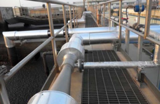
Shanghai Chemical Industry Park project data records: wastewater treatment capacity is 50,000 tons/day, COD load is 30 tons/day; the ozone process uses 6000 kg of pure oxygen daily to produce ozone, the oxygen content of the tail gas after ozone contact is 5400 kg/day, and the furthest distance from the ozone pool to the aerobic pool is 380 m.
This project employs six GW1200 Venturi injectors and twelve sets of GWB02-140-Air/O2 secondary jet enhancement devices. The negative pressure created by the Venturi injectors draws in oxygen-containing exhaust gas. Based on a 90% oxygen utilization rate, the data calculates that 4860 kg/d of oxygen can be supplied to the aerobic tank, and records a 25% reduction in power consumption under the current treatment load.
Frequently Asked Questions
Where Does the Negative Pressure in a Venturi Injector Come From?
The negative pressure comes from the high-speed jet formed after the pressurized fluid passes through the nozzle and its pressure drop. As long as the pressure near the inlet is lower than the supply pressure of the external gas or liquid, the passive fluid will enter the Venturi injector under the influence of the pressure difference.
Does the Venturi Injector Body Require a Motor?
The Venturi injector does not have a rotating impeller; the device operates using pressurized motive fluid. However, the entire system usually still requires a circulating water pump or an existing pressure network to provide flow and pressure.
Why Can't a Venturi Injector Intake Gas Even with a Vacuum?
Inlet power conditions, outlet back pressure, gas-liquid ratio, and flow channel scaling all affect the air intake volume. During troubleshooting, the power flow rate and pressure, downstream resistance, intake piping, and nozzles and throats should be checked simultaneously for scaling or blockage.
Is a Higher Gas-Liquid Ratio Always Better?
No. A smaller gas-to-water ratio generally makes it easier to form smaller, more evenly distributed bubbles, but the total mass transfer may be less; as the gas-to-water ratio increases, both the probability of large bubbles and the total mass transfer may increase simultaneously. Selection should be based on the treatment objective and operating costs, not solely on the ratio.
What is the Difference Between a Venturi Injector and an In-Pool Enhancement Nozzle?
The Venturi injector draws in external gas or liquid through a dedicated inlet to complete the primary mixing; the in-pool enhancement nozzle utilizes the residual pressure of the mixture at the Venturi injector outlet to attract surrounding pool water to participate in secondary jet mixing. Both can perform different stages of the function within the same system.
