
 Chengdu GreenWater Co.,Ltd.
Home
Library
Technical Literature
Use of Ejectors in Pharmaceutical Wastewater Treatment
Use of Ejectors in Pharmaceutical Wastewater Treatment
1. Project Overview
This project involved retrofitting the wastewater treatment system at Shangyu Xinhecheng Biochemical Co., Ltd. The aerobic treatment stage consists of two tanks—the north tank and the south tank—operating in parallel, with a total treatment capacity of 1500 m³/d, or 62.5 m³/h. The existing diffused-aeration system had lost efficiency after prolonged use. Operating costs were high, dissolved oxygen levels were inadequate, and the system could no longer meet its design targets. To improve effluent quality and reduce treatment costs, the customer decided to retrofit the north tank with ejectors that could be installed without interrupting wastewater treatment.
The photograph below shows the ejector installation.
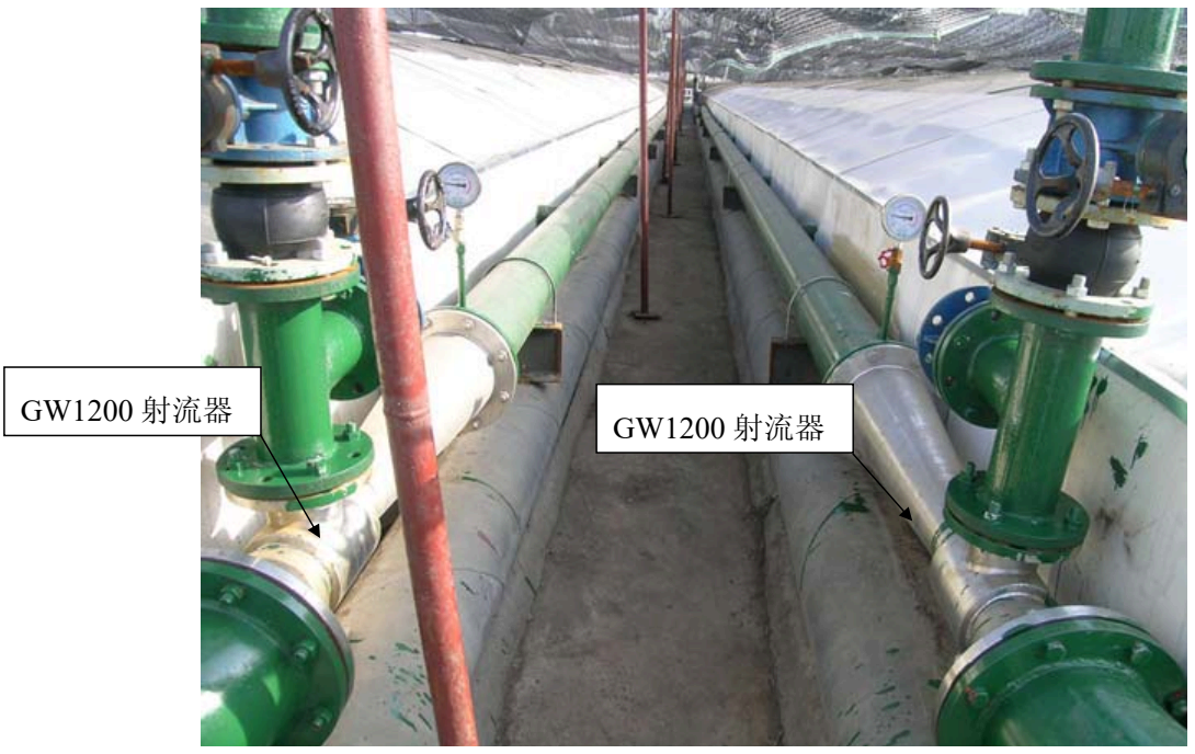 GW1200 ejector
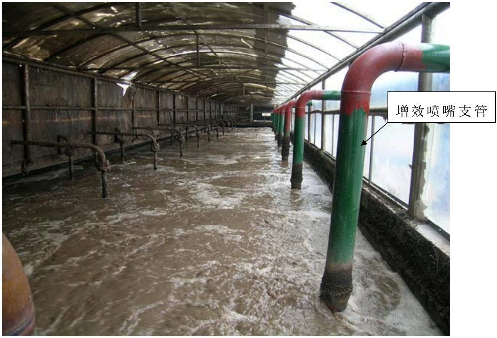 Booster-nozzle branch pipe
2. Implementation
After commissioning, water quality improved in the south aerobic tank but deteriorated in the north tank. An investigation attributed this difference to the following three issues, rather than to the GW ejectors or their design.
1. Insufficient and Uneven Air Distribution
For a given air-supply piping network, the resistance coefficients determine how air is distributed among the branches, regardless of the aeration method. At a total air supply rate of 18720 m³/h, the DN250 pipe serving the ejectors received 1540.22 m³/h. A single GW1200 ejector can draw in 324 m³/h at 49 kPa, giving a total air intake capacity of 2268 m³/h for seven units. The existing pipe therefore could not supply enough air to meet the ejectors’ requirements.
To increase the air supply to the north tank, its air-supply pipe was upgraded from DN250 to DN350.
2. Uneven Wastewater Distribution
A shared inlet channel distributes wastewater between the north and south aerobic tanks. The top of the channel is at the tanks’ normal design water level, as shown in the cross-section below.
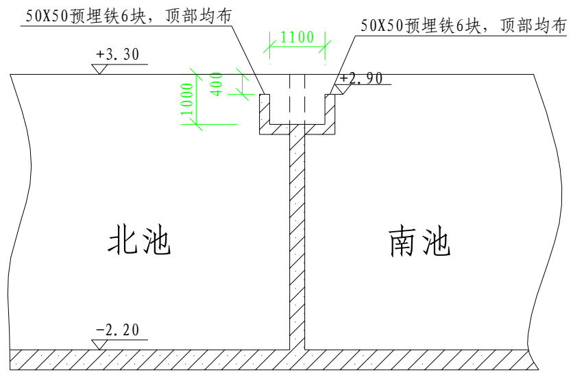 Six 50 × 50 embedded plates, evenly spaced along the top
North tank
South tank
During operation, air introduced into the tanks raises the actual water level slightly above the top of the inlet channel, affecting its discharge. Before the retrofit, both tanks used diffused aeration. With equal air supply rates, their water levels and wastewater inflows were approximately equal. After the retrofit, the air supply became uneven: the north tank received less air and the south tank received more. The greater volume of air in the south tank, combined with the vigorous surface motion caused by diffused aeration, raised its water level more than that of the north tank. The lower water level in the north tank consequently caused it to receive more wastewater than the south tank.
The diagram below illustrates wastewater distribution between the two tanks.
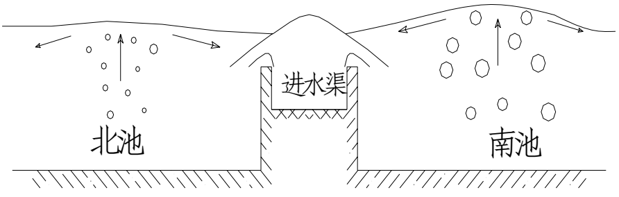 Inlet channel
North tank
South tank
The north tank thus received less air while treating more wastewater than the south tank, further impairing its treatment performance. Water quality deteriorated in the north tank while improving in the south tank.
To distribute the wastewater evenly, the inlet-channel weir plates were raised so that both tanks received wastewater by overflow from a higher level. This equalized the inflow to the two tanks, even when their air supply rates differed substantially.
The proposed solution is shown below.
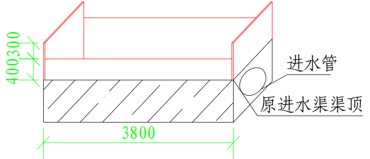 Inlet pipe
Original inlet-channel top
3. Pump Cavitation
Insufficient air supply to the north aerobic tank led to inadequate oxygen delivery. To improve its effluent quality, the treatment plant also operated some of the existing diffused-aeration equipment alongside the jet-aeration system. Diffusers were installed densely throughout the tank, including directly below and around the pump suction pipe. When these diffusers operated, their vertically rising bubbles entered the pump through the suction pipe, causing pump cavitation. The jet-aeration booster nozzles, by contrast, are horizontally separated from the pump suction pipe. The air–water mixture discharged from these nozzles follows a forward and upward parabolic path, keeping the bubbles away from the pump suction inlet and preventing pump cavitation.
One solution is to fit a large bubble-exclusion shroud around the pump suction pipe, keeping bubbles outside the shroud and preventing them from entering the pipe. Alternatively, the suction port of a small vacuum ejector can be connected to the top of the pump suction pipe to remove trapped air and prevent cavitation during pump startup.
The proposed solutions are shown below.
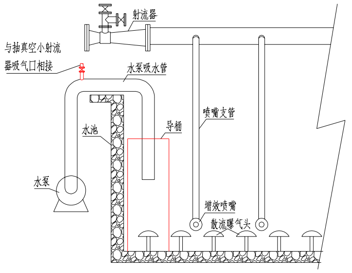 Ejector
To vacuum-ejector
suction port
Pump suction pipe
Tank
Shroud
Nozzle branch pipe
Pump
Booster nozzle
Air diffuser
3. Summary
After these issues were resolved, effluent COD from the north aerobic tank was generally 1200–1300 mg/L, and dissolved oxygen was 3–7 mg/L, meeting the design water-quality targets. The consistently high dissolved oxygen level indicated that the north tank’s aeration system still had spare capacity.
The north tank’s average energy consumption per kilogram of COD removed was 1.37 kWh/kg COD, with a minimum of 0.89 kWh/kg COD. The corresponding figures for the south tank were 1.69 and 1.1 kWh/kg COD. At the same influent load and amount of COD removed, average power consumption was 191.3 kW for the south tank and 148.9 kW for the north tank. The north tank therefore consumed 22% less energy on average, achieving the intended energy savings.
