
 Chengdu GreenWater Co.,Ltd
Home
Library
Media
Ejector Installation Guide
Ejector Installation Guide
Chengdu GreenWater Co., Ltd.
1. Overview
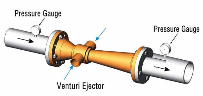
Venturi jet is a high-efficiency jet device. The working (power) fluid under pressure enters the injection chamber from the inlet of the jet to form a high-speed jet fluid. The high-speed fluid generates a pressure drop, causing the material to be added (liquid/gas) to be sucked in from the suction port and enter the working fluid. The mixed liquid reaches the outlet through the diffusion section, and the flow rate slows down and the pressure rises (but is lower than the inlet pressure). As long as there is a small pressure difference between the inlet and outlet, a negative pressure can be formed to suck in liquid or gas.
The structure of the jet aeration system includes ejector, efficiency nozzle (secondary ejector), circulating water pump, etc. It is suitable for various water depths, maintenance-free, easy to install and construct, and can be constructed and modified without water discharge. The same set of equipment can use different gas sources such as air, fan-pressurized air or pure oxygen to meet processing load fluctuations.
2. Installation method
2.1 Installation outside the pool
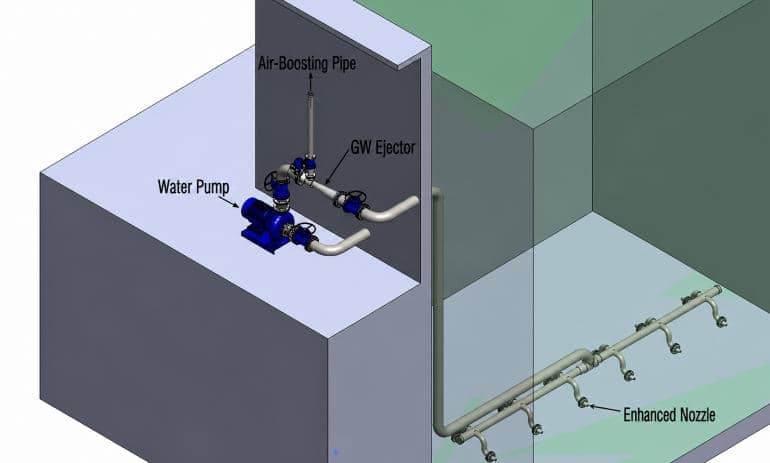
According to the water pump, the installation outside the pool is mainly divided into pipeline pump, vertical pump and self-priming pump dry installation. It is suitable for newly built or renovated above-ground aeration tank and underground aeration tank structures. The installation is very fast and convenient, and the pipeline is simple. Only the water pump needs to be maintained, and the ejector and booster nozzle do not require maintenance for long-term operation.
Figure a: Horizontal pump dry installation
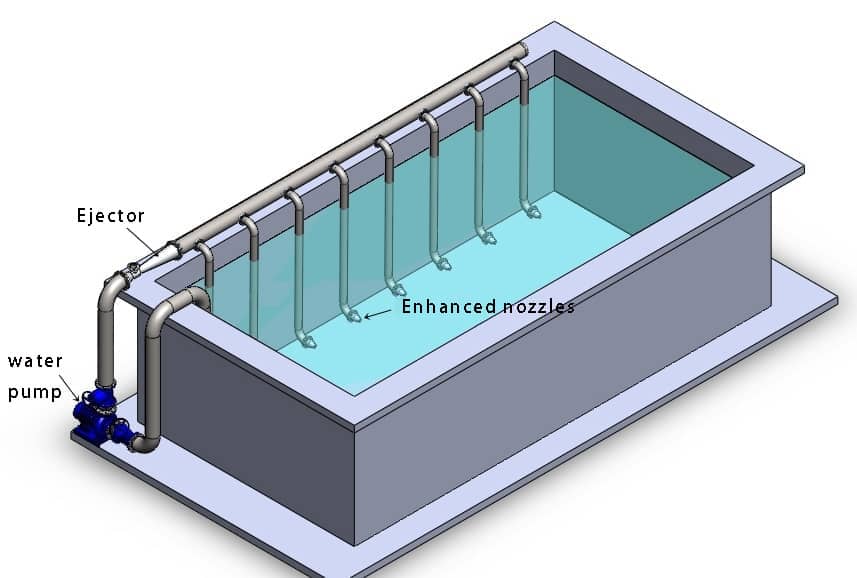
Figure b: Dry installation of self-priming pump
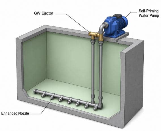
Figure c: Air blast and pressurized installation
2.2 Pipeline installation
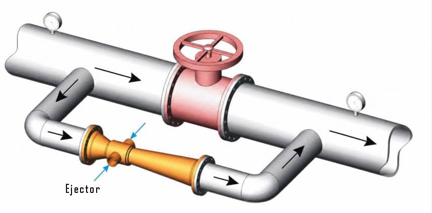
If the power water volume and pressure on the pipeline are within the working range of the selected ejector, the ejector can be installed directly on the main pipeline; when the power flow and pressure remain unchanged, the ejector will inhale a constant amount of gas or liquid.
If the power flow on the main pipeline is greater than the working flow of the selected ejector, the ejector can be installed on the bypass, and the flow and pressure through the ejector can be adjusted through the main flow regulating valve to adjust the suction volume or liquid volume.
2.3 GWQ/B jet aerator installation form
GWQ/B jet aerator is mainly composed of water pump, Venturi jet, efficiency nozzle and secondary jet guide tube (optional). The system is simple and does not require blowers, complex pipelines and other equipment; the structure is compact and easy to install. During maintenance, only the water pump is required to be repaired. Repairing one piece of equipment does not require stopping the operation of other equipment.
GWQ: Submersible jet aerator, which can be hoisted into the pool;
GWB: Dry installation outside the jet aeration tank.
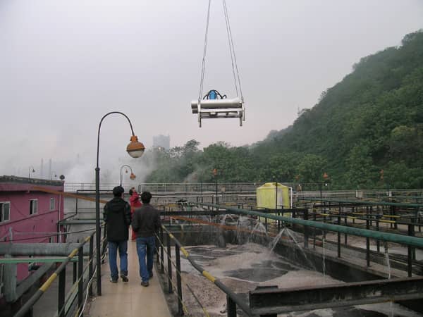
GWQ submersible jet aerator hoisting
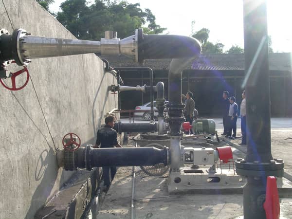
Dry installation outside GWB jet aeration tank
2.4 GW integrated jet aeration unit
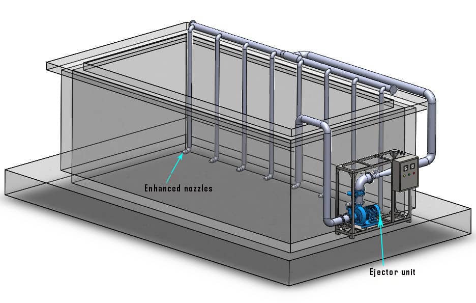
GW jet integrated equipment uses liquid as the working medium and uses the Venturi principle to generate negative pressure when the liquid is sprayed at high speed, so that the mixed liquid (sewage + sludge) sucked in by the water pump is jet-mixed with air/oxygen in the ejector to form a supersaturated oxygen mixed liquid. It is small in size, compact in structure and movable. It is suitable for various renovation or new aeration and oxygenation occasions. It can also be used in renovation projects where water is not stopped or water is discharged.
3. Self-priming height and suction port layout
When the self-priming jet aeration jet is installed outside the pool, the height of the suction port of the jet should be higher than the water surface.
If the ejector is installed inside the pool, or installed outside the pool but the height of the suction port is lower than the water surface, the suction port of the ejector needs to be extended above the water surface.
4. Arrangement of efficiency-enhancing nozzles in the aeration tank
The service distance in the spray direction of the booster nozzle is generally 5 m to 6 m. When selecting, first determine the nozzle specifications and quantity according to the unit configuration table, and then filter according to the pool layout.
4.1 Pool width ≤ 6 m
Arranging a row of synergistic nozzles in the width direction of the pool can meet the service distance in the spray direction; in the length direction of the pool, arrange the nozzle spacing allowed for each model (for example, N70 spacing ≤ 3.5 m, N70B/N70C/N60 spacing ≤ 3 m, N40/N30 spacing ≤ 2.5 m).
4.2 Pool width>6m
Multiple rows of synergistic nozzles need to be arranged in the direction of the pool width. The number of rows can be estimated according to N=pool width/5 m (rounded); after the number of nozzles is allocated according to the row number, check whether the spacing in the length direction of the pool meets the requirements.
5. Key points for startup and shutdown after installation
After the correct installation is completed, the valve must be started and stopped according to the correct status, especially the blowing and pressurizing method to prevent air from entering the water pump body or water from the fan/air duct.
5.1 Self-priming jet aeration
Startup: Start the water pump according to the water pump manual and confirm that it is running in the forward direction; the submersible pump can measure the wind speed at the self-suction port, and the motor rotation can be observed for the pump outside the pool; if the air suction port is obvious, the operation is normal.
Shutdown: Stop the water pump according to the water pump manual.
5.2 Air blast and pressurized jet aeration
The initial state after the equipment is installed: the water pump and fan are stopped; the blast air inlet valve FI is closed; the self-priming bypass valve SI is fully open; the blower vent valve FV is open.
1. When using the blast and pressurization mode to start the water pumps one by one, the self-priming bypass valve of the ejector of the unstarted water pump must be opened.
2. It is prohibited to use a blower alone to aerate through the jet without turning on the jet pump.
3. After confirming that the self-priming is working normally, open the blast air inlet valve FI and the blower, close the self-priming bypass valve SI, and gradually close the vent valve FV.
4. Shutdown: When the system shuts down, first turn on the SI exhaust, then stop the fan and turn off the FI, and finally stop the water pump; do not stop the water pump when the fan is running and FI is on.
5. When the blower is stopped, the ejector corresponding to the water pump that is not stopped/not started should close FI and open SI to prevent siphonage from causing pool water to enter the blast pipe.
Valve opening and closing reference table
| Condition | FO | FV | FI | SI | PI | PO |
|---|---|---|---|---|---|---|
| Water pump stops/fan stops | close | open | close | open | close | close |
| Water pump on/fan off | close | open | close | open | open | open |
| Water pump on/fan on | open | close | open | close | open | open |
| Water pump stops/fan starts (fault) | open | close | close | open | close | close |
FO blower outlet valve; FV vent valve; FI blower air inlet valve; SI self-priming bypass valve; PI/PO water pump inlet/outlet valve.
5.3 Jet plus ozone
After the equipment is installed, the water pump is stopped and the ozone inlet valve is closed. After starting the water pump and confirming that the self-priming is normal, close the self-priming air valve and then open the ozone air inlet valve. When stopping, first close the ozone inlet valve, then close the water pump and valve according to the instructions.
6. Pay attention to the installation site of pure oxygen/diving equipment
Engineering practice (coking wastewater pure oxygen aeration test) shows:
1. After the oxygen supply equipment, busbar and starting cabinet are in place, the oxygen supply pipeline is laid, and the diffuser is lifted into the sewage pool with a crane;
2. In order to prevent the original air aeration pipe from being crushed, a support platform should be set up underwater;
3. When installing in water, it is recommended to turn off the blower briefly to eliminate the influence of water and air flow turbulence and ensure that the equipment is correctly positioned;
4. Oxygen-related equipment and pipelines must be cleaned and degreased according to the properties of oxygen, and must comply with oxygen pipeline installation specifications.
7. Installation of jet pump for foundation pit dewatering (related applications)
7.1 Light well points
The jet pump and supporting centrifugal pump are arranged above the ground of the foundation pit: each well point pipe is connected to the suction port of the jet pump through the main pipe, and the centrifugal pump uses clean water circulation. The ultimate suction depth of the jet pump is about 10 m, and the normal precipitation depth is about 8 m.
Installation and debugging process: Install the ground centrifugal pump, jet pump, water tank and ground pipeline; determine the well point layout, sink the well point pipe after drilling and fill it with sand filter material; test to ensure that the well point pipe does not leak air or water before putting it into use.
7.2 Jet well point (jet deep well pump)
The jet pump is placed in the jet well pipe (integrated jet deep well pump), and the burial depth is determined according to the precipitation depth; the suction depth can usually be considered to be about 4 to 6 m lower than the jet pump, and a high-pressure water pump is generally required.
Installation and debugging process: Install ground centrifugal pumps, water tanks and ground pipelines; determine the well point layout, sink the injection well point pipes after drilling and fill with sand filter material; test to ensure there is no air leakage or water leakage before putting it into use.
8. Troubleshooting related to installation
The ejector itself cannot generate a pressure difference, but relies on the pressure loss of the power source through the ejector and the pipeline to form a pressure difference. When it cannot work normally, the installation position can be appropriately changed to meet the pressure difference requirements, and it is recommended to install pressure gauges at the inlet and outlet.
1. The inlet pressure is low and the pressure difference is not enough: increase the pump head or add a pressure pump;
2. The matching inlet and outlet connecting pipe is too small: use a pipe that is consistent with the inlet and outlet of the ejector;
3. There is a blockage in the connecting pipe: clear the blockage;
4. The suction pipe is dirty or blocked: blow it clean and remove the blockage;
5. Dimensional changes caused by internal dirt during long-term operation: usually soak in 30% hydrochloric acid for about 30 minutes to clean, and then rinse with clean water.
Company Information
Company website: https://cd-greenwater.com
Technical contact number: 028-85130135
Customer service contact number: 18515915124
Contact email: jane1984@cd-greenwater.com
Address: No. 191, Section 1, Changcheng Road,
Xihangang, Shuangliu District, Chengdu City
