
 Chengdu GreenWater Co.,Ltd
Home
Library
Media
How An Ejector Creates Vacuum
How Does an Ejector Create a Vacuum?
An ejector uses high-pressure motive fluid passing through a nozzle to form a high-speed jet. After the motive fluid accelerates, the static pressure near the nozzle exit and inside the suction chamber drops. When this pressure falls below the pressure in the vessel being evacuated, gas enters the ejector through the suction inlet. The entrained gas mixes with the motive fluid in the throat, then the mixed flow decelerates through the diffuser section, recovering part of its pressure before being discharged. As gas is continuously carried away, the pressure inside the evacuated vessel steadily decreases, thereby creating a vacuum.
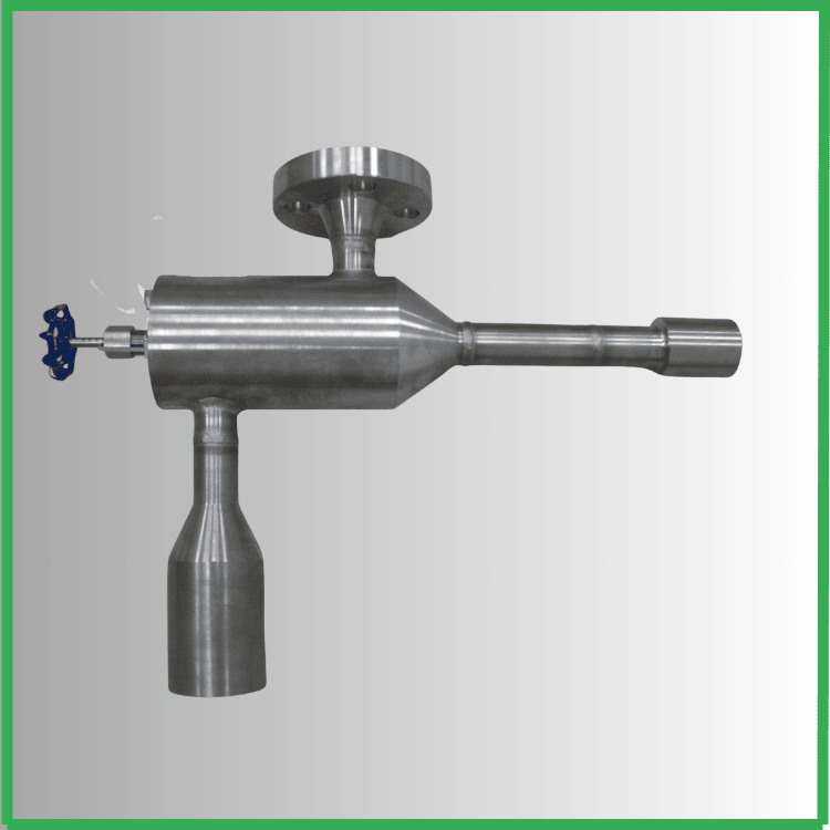
Four Steps of Vacuum Creation by an Ejector
1. Motive Fluid Enters the Nozzle
Water, air, or steam at a certain pressure and flow rate enters the ejector. The motive fluid can be supplied by a pump, compressor, or steam system.
2. The Nozzle Converts Pressure into Velocity
As the motive fluid passes through the converging nozzle, the flow area decreases, the velocity increases rapidly, and the static pressure drops simultaneously. The high-speed jet creates a low-pressure zone in the suction chamber.
3. The Low-Pressure Zone Draws in Gas
When the pressure in the suction chamber is lower than the pressure inside the equipment or vessel being evacuated, the pressure differential drives gas through the suction inlet. The high-speed jet continuously entrains and carries away this gas, gradually reducing the number of gas molecules in the vessel and steadily lowering the internal absolute pressure.
4. The Mixed Flow Passes Through the Diffuser and Is Discharged
The motive fluid and entrained gas exchange momentum and mix in the throat. After the mixed flow enters the gradually expanding diffuser section, its velocity decreases and part of the kinetic energy is converted into pressure energy, enabling the mixed flow to overcome the discharge back pressure and be expelled.
The entire process can be summarized as:
Motive fluid pressure energy → High-speed nozzle jet → Low-pressure zone formation and gas entrainment → Throat mixing → Diffuser pressure recovery and discharge
Is Vacuum "Sucked" Out?
Strictly speaking, an ejector does not directly create an empty cavity. Rather, it uses the pressure differential and high-speed jet to continuously remove gas from the vessel. When the rate at which gas is expelled exceeds the rate at which external air leaks in or process gas is generated, the pressure inside the vessel decreases, forming a sub-atmospheric vacuum condition.
Therefore, the ultimate vacuum level an ejector can achieve depends on the balance between its gas extraction capacity and the system's air leakage, vapor generation, and other gas loads.
Main Structural Components of an Ejector
| Component | Function |
|---|---|
| Motive Inlet | Receives high-pressure water, compressed air, or steam |
| Nozzle | Converts pressure energy into a high-speed jet |
| Suction Inlet | Connects to the vessel or pipeline to be evacuated |
| Suction Chamber | Forms a low-pressure zone and receives the entrained gas |
| Throat | Allows momentum exchange and mixing of the motive fluid and entrained gas |
| Diffuser | Reduces flow velocity, recovers part of the pressure, and drives the mixed flow to discharge |
What Factors Affect Vacuum Level?
1. Motive Fluid Pressure and Flow Rate
If the motive pressure or flow rate is insufficient, the nozzle cannot produce the design-specified high-speed jet, and the suction chamber pressure cannot be adequately reduced.
2. Nozzle and Throat Dimensions
The nozzle exit area, throat area, and their ratio determine the ejector's gas extraction capacity, vacuum level, and allowable discharge pressure. If the dimensions are mismatched, an ideal vacuum may not be achieved even with high motive pressure.
3. Discharge Back Pressure
Excessively narrow, long, or blocked discharge piping, or excessive downstream pressure, will impede the discharge of the mixed flow. When the back pressure exceeds the design range, gas extraction capacity drops, and in severe cases, vacuum may be lost entirely.
4. Suction Line Resistance
Excessive suction line length, undersized pipe diameter, too many elbows, or insufficient valve opening all increase resistance, causing the vacuum measured at the equipment inlet to differ from the actual vacuum inside the evacuated vessel.
5. System Air Leaks
Leaks at flanges, valves, seals, instrument connections, or welds continuously introduce outside air into the system. If the leakage rate is too high, the ejector may never reach the target vacuum level.
6. Gas Properties and Temperature
The molecular weight, temperature, moisture content, and condensability of the gas being extracted all affect ejector performance. When using steam ejectors, the quality of the motive steam and the condensation conditions are also critically important.
Why Don't Ejectors Need Moving Parts?
Ejectors do not rely on impellers or pistons to extract gas. Instead, they use the energy of the motive fluid itself to accomplish acceleration, entrainment, and transport. Consequently, the ejector body typically has no moving parts, offering advantages such as simple construction, low maintenance, and the ability to handle wet or corrosive gases.
However, "no moving parts" does not mean no energy is consumed. The motive water, compressed air, or steam must all be supplied by external systems, and their energy consumption should be accounted for in the overall vacuum system calculation.
What If the Ejector Cannot Establish a Vacuum?
Check the following in sequence:
1. Whether the motive fluid pressure and flow rate meet the design values;
2. Whether the motive fluid valve and suction inlet valve are properly opened;
3. Whether the nozzle, throat, or discharge piping is blocked;
4. Whether the discharge back pressure exceeds the allowable range;
5. Whether the suction line and the evacuated system have air leaks;
6. Whether the vacuum gauge range, installation position, and readings are correct;
7. Whether the actual gas load exceeds the ejector's design extraction capacity;
8. Whether the nozzle is worn, corroded, or scaled.
Frequently Asked Questions
What is the difference between an ejector and a vacuum pump?
A mechanical vacuum pump expels gas through rotating or reciprocating components; an ejector uses a high-speed motive fluid to entrain gas. Ejectors have a simpler construction but require a continuous supply of motive fluid.
What motive fluids can be used in an ejector?
Common motive fluids include pressurized water, compressed air, and steam. The choice should be based on the target vacuum level, extraction capacity, gas properties, on-site energy availability, and material requirements.
Does higher motive pressure always mean a higher vacuum level?
Not necessarily. An ejector needs to operate near its design operating point. While excessively low motive pressure degrades performance, blindly increasing pressure may only increase energy consumption without further improving the vacuum level. The nozzle, throat, gas load, and discharge back pressure must all be mutually matched.
Can an ejector achieve absolute vacuum?
No. In any real system, gas loads, leaks, flow losses, and equipment performance limits always exist. In engineering practice, the target should be expressed as an absolute pressure or a vacuum level under specified conditions; "vacuum" should not be interpreted as pressure equal to zero.
Conclusion
The core mechanism by which an ejector creates a vacuum is: allowing the motive fluid to form a high-speed jet through the nozzle, establishing a low-pressure zone in the suction chamber, and continuously entraining, mixing, and discharging the gas being extracted. Whether the target vacuum level can be achieved depends not only on the motive pressure, but also on the nozzle and throat geometry, gas extraction load, suction resistance, discharge back pressure, and system airtightness.
Company Information
Company Website: https://cd-greenwater.com
Technical Contact Number: 028-85130135
Customer Service Contact Number: 18515915124
Contact Email: jane1984@cd-greenwater.com
Address: No. 191, Section 1, Changcheng Road,
Xihanggang, Shuangliu District, Chengdu City
