
 Chengdu GreenWater Co.,Ltd
Home
Library
Technical Literature
Selection Guide for Venturi Jet Units for Ozone Dosing
Selection Guide for Venturi Jet Units for Ozone Dosing
Selecting an ozone dosing system requires more than checking how much gas an injector can draw in. First establish the ozone mass dose and gas concentration, then assess gas flow, motive water flow, tank depth, backpressure, contact time, materials and off-gas treatment as one system. This guide draws on GreenWater GW product information, design guides, FAQs and project records.
Initial Selection Guidance
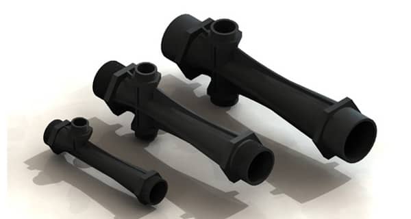
For clean water or general industrial wastewater, evaluate 316L first. For acidic or complex corrosive media, check the chemical compatibility of PVDF, PTFE and all sealing materials individually. Use ozone gas flow and the gas-to-water ratio for preliminary sizing, then verify inlet pressure, outlet backpressure, suction-line losses and contact-tank conditions.
Why Does Ozone Dosing Need a Suitable Injector?
Ozone is a strong oxidizer. Inadequate ozone resistance in the injector body, seals, suction piping, valves, wetted instrument parts, lubricants or adhesives can lead to embrittlement, cracking, corrosion or leakage. A suitable injector therefore needs both appropriate hydraulic performance and ozone-resistant materials, with seals and piping assessed as part of the same material system.
Effective ozone use is limited by solubility, decomposition and the reaction demand of the water. Introducing ozone into water does not by itself ensure mass transfer: large bubbles, short rising paths, insufficient contact time or excessive backpressure can increase off-gas losses. Motive water creates a high-speed, low-pressure zone at the Venturi throat, drawing in ozone and shearing it into fine bubbles. The diffuser recovers part of the pressure before the mixture enters the contact zone or bottom-mounted enhancement nozzles for secondary mixing.
For operation, establish stable suction with motive water before enabling ozone. At shutdown, stop ozone before stopping the circulation pump. Provide backflow protection and assess generator outlet pressure, suction-line losses and tank backpressure to prevent water from entering ozone piping.
Material Selection for Ozone Service
Benefits and Limits of 316L
316L combines ozone resistance, mechanical strength, pressure and temperature capability, and weldability. It is suitable for rigid pipework, flanged connections and long-term industrial service. The referenced corrosion guidance describes 304 for lower ozone concentrations and 316L for higher concentrations. Its cleanable surface also suits pharmaceutical, food, reclaimed-water and industrial-water systems.
316L is not universally corrosion-resistant. High chloride levels can damage its passive film and cause pitting. Acids, halides and mixed high-salinity wastewater require assessment of concentration, temperature, velocity, crevices and weld condition. Fluoropolymers, corrosion-resistant alloys or reliable protective linings may be needed.
PTFE, PVDF and 316L Compared
| Material | Main advantages | Suitable applications | Selection considerations |
|---|---|---|---|
| 316L | High strength, pressure and temperature capability; machinable, weldable and cleanable; suitable for high-concentration ozone | Clean water, reclaimed water and general industrial wastewater; metal flanges and higher pressure or temperature | Reassess pitting and crevice corrosion with chlorides, high salinity or strong acids; include welds and seals |
| PVDF | Good resistance to ozone and many acids and salts; greater rigidity than PTFE for injector bodies and fittings | Ozone advanced oxidation with dilute acids, salts or nonmetallic wetted components | Check the specific chemical, concentration, temperature and pressure; consider thermal expansion, connection stress and long-term creep |
| PTFE | Broad chemical inertness and resistance to ozone and many aggressive media; useful for seals, gaskets and linings | Seals, gaskets, hose linings and selected wetted parts in highly corrosive service | Lower rigidity and creep resistance than metal or PVDF; pressure-bearing bodies need dedicated design; cold flow can relax seals |
First eliminate incompatible materials based on fluid composition and the worst-case temperature. Then compare pressure capability, connection size, installation loads and maintenance. Even a correctly selected body can fail as a system if O-rings, hoses, check valves, flowmeters or adhesives are not ozone-resistant.
Factors Affecting Ozone Utilization
Gas-to-Water Ratio, Depth, Contact Time and Temperature
- Gas-to-water ratio: This is ozone-bearing gas volume flow divided by motive water volume flow. At the same depth and inlet pressure, a lower ratio generally improves bubble dispersion and ozone transfer, but needs more circulating water and pump power for the same gas flow. The referenced design guide gives economic operating ranges of about 15%–20% at 5 m depth, 20%–25% at 8 m, and 30%–35% at 10 m.
- Water depth: Longer bubble paths, hydrostatic pressure and contact time support transfer. At a 30% gas-to-water ratio and approximately 1.4 kgf/cm² injector inlet pressure, the design guide reports ozone transfer efficiencies of about 87%, 92% and 98% for depths of 5 m, 8 m and 10 m respectively. Compare these benefits with excavation and life-cycle costs.
- Contact time: Allow for both reaction demand and uniform tank mixing. GW injectors provide rapid primary mixing, but when treatment flow exceeds motive water flow, the circulation ratio and whole-tank mixing time must also be checked. Draft tubes and secondary jets can extend the gas–liquid contact path to create an equivalent depth.
- Water temperature: Lower temperature generally favors ozone dissolution and retention. Higher temperature reduces gas solubility and accelerates ozone decomposition, while reaction rates also depend on pollutants, pH and catalysts. Check mass transfer at the highest summer water temperature and establish actual ozone demand through project testing.
Salinity, water quality, pH, ozone concentration, inlet pressure, outlet backpressure and suction-line losses also affect utilization. Clean-water data should not directly replace wastewater performance data.
GW Pilot Results: Ozone Utilization Above 99%
The referenced pilot records describe a GW200 DN50 injector tested with clean water in an approximately Φ1000 × 1500 mm reactor. Separate oxygen and ozone tests achieved oxygen transfer above 90% and ozone utilization above 99%. These results apply to the matched clean-water pilot conditions and are not an unconditional guarantee for every project. Wastewater performance also depends on temperature, pH, salinity, pollutant reaction rates, gas-to-water ratio, depth, tank flow patterns and off-gas measurement methods. Project commitments should be based on water-sample testing and a complete mass balance.
How Transverse Gas Injection Improves Mass Transfer
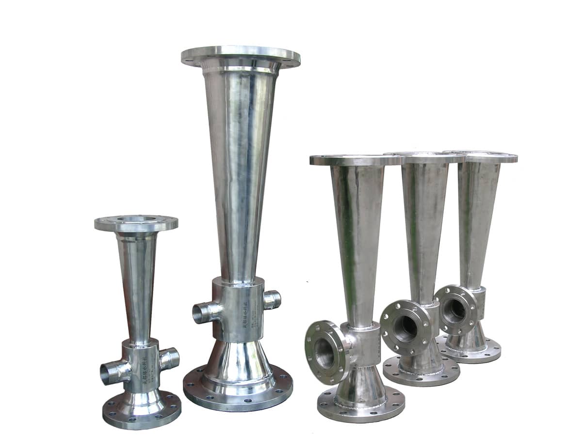
In the GW Venturi arrangement, ozone enters through a side suction port approximately perpendicular to the high-speed motive water jet. Strong shear, velocity gradients and turbulence divide the incoming gas and incorporate it into the main flow, shortening the distance between suction, bubble breakup and mixing and reducing the opportunity for large bubbles to escape.
The mixed flow then enters the diffuser for partial static-pressure recovery before secondary jetting through enhancement nozzles. The product literature describes secondary jets entraining about four to five times the surrounding water volume, extending circulation and contact paths while using residual head for further bubble dispersion. Transverse suction promotes rapid breakup at the throat; secondary jets distribute the mixture in the tank. Both need to be designed together with tank depth, draft tubes and contact time.
Application Examples
Example 1: Ozone advanced oxidation with dilute sulfuric acid and a PVDF injector
This is an anonymous selection scenario. Complete completion or acceptance records were not available in the reference material, so it illustrates material selection and system checks without claiming verified removal rates or service life.
The contact liquid contains dilute sulfuric acid and continuously contacts ozone. Selecting stainless steel solely on clean-water assumptions can overlook corrosion caused by acid concentration, temperature, impurities and crevices. The scenario uses PVDF for the main wetted injector body, with PTFE gaskets or seals, or other seals confirmed compatible with ozone.
The arrangement is circulation pump → PVDF Venturi injector → contact tank/secondary jets → off-gas treatment. Check:
- Sulfuric acid mass fraction, maximum water temperature, chlorides, solvents and other impurities.
- Ozone mass dose and generator outlet concentration, converted to standard gas flow.
- Inlet pressure, outlet backpressure, suction-line losses and backflow protection.
- Compatibility of the PVDF body, joints, valves, instruments and seals under the worst conditions.
- Off-gas monitoring and destruction, with contact time determined by water-sample testing.
The selection must satisfy chemical compatibility and structural pressure requirements together. PVDF forms the main wetted structure; PTFE is especially useful for seals and linings. Supports and flange loads must avoid long-term creep and stress concentration.
Example 2: Ozone off-gas reuse with a reported 25% reduction in aeration power
The Shanghai Chemical Industry Park Sino-French Water project had a treatment capacity of 50,000 m³/d and a COD load of approximately 30 t/d. Its advanced oxidation process produced ozone from pure oxygen, consuming about 6,000 kg of oxygen per day (approximately 4,200 Nm³/d), with an ozone conversion rate of about 10%. Off-gas still contained approximately 90% oxygen and had previously been discharged.
The retrofit conveyed this off-gas to upstream aerobic biological tanks for oxygen aeration over a maximum distance of approximately 380 m. Six GW1200 injectors and twelve GWB02-140-Air/O₂ secondary jet enhancement assemblies drew about 5,400 kg/d of oxygen from the off-gas. At 90% oxygen utilization, the calculated oxygen supply to the aerobic tanks was approximately 4,860 kg/d.
The original aerobic tanks had twelve 75 kW surface aerators. Under the treatment load at that time, off-gas reuse reduced aerator operating time and actual power use by 25%; the project passed acceptance and met its design requirements. This was a project-specific result. Other plants need a mass balance covering off-gas oxygen concentration, piping losses, suction capacity, oxygen demand and existing aerator operating strategy.
Selection Data
Calculation Method
- Ozone-bearing gas flow: Qg = M3 / C3, where Qg is standard gas flow (Nm³/h), M3 is ozone mass dose (kg/h), and C3 is generator outlet ozone concentration (kg/Nm³).
- Initial motive water flow: Ql = Qg / R, where R is the gas-to-water volume ratio. Start with the depth-dependent reference range, then optimize for energy use and transfer targets.
- Select a model or parallel units covering Ql, and verify inlet pressure, outlet backpressure and suction capacity.
- Establish ozone demand, contact time and off-gas targets through water-sample testing or reliable process data.
GW200–GW3600 Preliminary Selection Parameters
The reference ozone dosing ranges below are for preliminary selection only, calculated at 8 m water depth, a 20%–25% gas-to-water ratio and an ozone concentration of 100 g/Nm³: reference dose = motive water flow × gas-to-water ratio × 0.1 kg/Nm³. At 120 g/Nm³, multiply the mass-dose figures by 1.2. Confirm the final model against manufacturer performance curves and actual backpressure.
| Model | Main connection | Length (mm) | Motive water (m³/h) | Inlet pressure (kgf/cm²) | Reference ozone-bearing gas flow (Nm³/h) | Reference ozone dose (kg/h) |
|---|---|---|---|---|---|---|
| GW200 | DN50 | 267 | 7.5–33 | 0.35–7.03 | 1.50–8.25 | 0.15–0.83 |
| GW300 | DN80 | 396 | 17–74 | 0.35–7.03 | 3.40–18.50 | 0.34–1.85 |
| GW400 | DN100 | 551 | 30–103 | 0.35–4.22 | 6.00–25.75 | 0.60–2.58 |
| GW600 | DN125 | 665 | 56–192 | 0.35–4.22 | 11.20–48.00 | 1.12–4.80 |
| GW800 | DN150 | 766 | 82–303 | 0.35–4.92 | 16.40–75.75 | 1.64–7.58 |
| GW1200 | DN200 | 1075 | 140–480 | 0.35–4.92 | 28.00–120.00 | 2.80–12.00 |
| GW3600 | DN300 | 1576 | 274–1010 | 0.35–4.57 | 54.80–252.50 | 5.48–25.25 |
Source discrepancy: The website parameter table gives a GW1200 minimum motive water flow of 140 m³/h, while the product brochure gives 130 m³/h. This table uses 140 m³/h. Before ordering, confirm the current manufacturer drawing and performance curves. Standard GW literature lists SUS304, SUS316 and SUS316L bodies; other materials require project-specific confirmation.
Minimum Information to Provide for Selection
- Treatment and circulation flow rates; contact tank length, width and effective depth.
- Ozone dose in kg/h or mg/L, and generator outlet concentration in g/Nm³.
- Gas-source pressure, suction-line length and diameter, fittings and allowable vacuum.
- Circulation pump flow and head, available inlet pressure and injector outlet backpressure.
- Temperature, pH, salinity, chlorides, acids, alkalis, solvents and suspended solids.
- Target ozone utilization, contact time, off-gas concentration and treatment method.
- Preferred materials, flange standard, installation orientation and maintenance space.
Contact Information
Chengdu GreenWater Technology Co., Ltd.
Telephone: 028-85130135
Email: jane1984@cd-greenwater.com
Sales / company telephone: 18515915124
