
 Chengdu GreenWater Co.,Ltd
Home
Library
Technical Literature
Integrated jet aeration unit selection guide
Integrated jet aeration unit selection guide
statement:
The design principles and chart data cited in this guide only apply to the ejector series products of Chengdu Green Water Technology Co., Ltd. It is not permitted and cannot be referenced by any other equivalent functional product or by anyone for any purpose. The company is not responsible for the results of any improper quotation and reserves the right to initiate litigation after infringement.
introduction
With the improvement of sewage treatment discharge standards, higher requirements have been put forward for the oxygenation efficiency, reliability and service life of biochemical aeration equipment. At the same time, for the purpose of reducing costs, sewage discharge units are increasingly paying attention to the power consumption of pollutant removal (such as kWh/kg (COD)) and maintenance and replacement costs. The jet mass transfer system has the characteristics of high efficiency, long-term stable and reliable performance, long life, suitable for various water depths, maintenance-free, low investment, easy installation and construction, and can be constructed and modified without water discharge. It provides efficient and reliable technical means to meet the needs of customers for sewage treatment.
The jet system conducted a complete industrial-scale test of pure oxygen aeration and air aeration in 2005, accumulated empirical data, and established a computational design model. On this basis, after many years of application practice in air aeration, ozone dosing and pure oxygen aeration, a mature product series system has been formed.
Although the jet system has a simple structure, it consists of an injector, a secondary injector, a circulating water pump, etc. Its mass transfer efficiency and power consumption are related to the following parameters:
1. Water depth
2. Air-to-water ratio
3. Hydraulic retention time
4. Import working pressure
5. Export working pressure
6. Water temperature
7. Salinity
8. Water quality
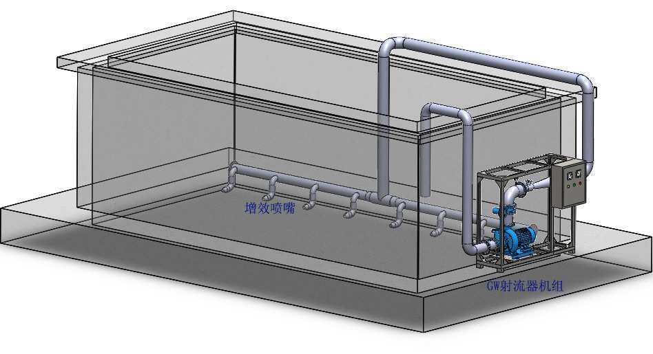
Therefore, in the design, it is necessary to ensure both high oxygen transfer efficiency and low power consumption. For non-professionals, it is a complicated and clueless matter.
The purpose of this selection guide is to provide basic guidance for design units or personnel to complete the preliminary selection of aeration equipment in the initial stage of project design. After the project is established, it is recommended to send it to Chengdu Green Water Technology Co., Ltd. to make suggestions for modifications in selection and design.
The selection of jet aerator includes three parts: ejector unit selection (the ejector unit is composed of a water pump and a ejector), efficiency nozzle selection, and fan selection (a fan is not required for self-priming jet aeration, but is required for blast and pressurized jet aeration).
1. Selection of ejector unit
A. Direct lookup table method
When the actual operating conditions of the project are consistent with the conditions given in the "Jet Unit - Self-priming/Blast Pressurized Oxygenation Selection Table" (i.e. water temperature 20°C, operating dissolved oxygen 2mg/L, salinity 0, coefficient θ=1.024; the remaining coefficients When α, β, Ω, and τ are 1) the same, there is no need to correct the calculated actual oxygen demand. According to the calculated actual oxygen demand and the water depth of the aeration tank, directly check the "Jet Unit-Self-priming/Blow Pressurized Oxygen Selection Table" (i.e. "Appendix 1" Jet unit - self-priming series oxygenation capacity selection table", "Attachment 2 Jet unit - blower and pressurization series oxygenation capacity selection table", hereafter referred to as attachment 1, attachment 2) to make selections.
Example 1: The pool type of a certain project is 8m×5m×4m (water depth), the operating temperature is 20°C, the salinity is 0, and the actual oxygen demand is 32kg (O₂)/h.
The actual operating conditions of this project are the same as those given in the table. There is no need to correct the calculated actual oxygen demand. You can directly look up the table (i.e. Attachment 1 and Attachment 2) for selection.
Look up the table: When the water depth is 4m, the actual oxygenation amount of the GW-T300C ejector unit for self-priming is 32.22kg (O₂)/h; the actual oxygenation amount of the GW-T200C ejector unit for blast and pressurization is 33.45kg (O₂)/h; both models of ejector units can meet the oxygen demand of the project.
Therefore, there are two types of GW aeration units for this project: ①GW-T300C, self-priming; ②GW-T200C, blast and pressurized.
B. Modified look-up table method
When the actual operating conditions of the project are different from the conditions given in the "Jet Unit - Self-priming/Blast Pressurized Oxygenation Selection Table" (i.e. water temperature 20°C, operating dissolved oxygen 2mg/L, salinity 0, coefficient θ=1.024; the remaining coefficients α, β, Ω, τ are 1), the calculated actual oxygen demand needs to be corrected first (see "Annex 4 Oxygenation Correction Calculation" for specific correction methods), and the correction is AOTR(T=20℃,β=1)value, and then based on the corrected AOTR(T=20℃,β=1)Check the table (i.e. Attachment 1, Attachment 2) according to the value to select the model.
Example 2: The pool type of a certain project is 8m×5m×4m (water depth), the operating temperature is 25℃, the salinity is 5‰, and the actual oxygen demand is 32kg (O₂)/h.
The actual operating conditions of this project are different from those given in the table. The oxygen demand AOTR under the actual operating conditions needs to be corrected to AOTR first.(T=20℃,β=1)After checking the value, conduct table lookup (i.e. Attachment 1, Attachment 2) for model selection.
Find out from "Annex 5 Saturated dissolved oxygen concentration at different salinities and operating temperatures (mg/L)" that the saturated dissolved oxygen concentration at 25°C and a salinity of 5‰ is C*ST=8.01mg/L
AOTR=AOTR(T=20℃,β=1)/7.08×(β×C*ST-COP) (Note: For the formula, see Appendix 4 for oxygenation correction calculation)
i.e. AOTR(T=20℃,β=1)=AOTR×7.08/(β×C*ST-COP)
=32×7.08/(1×8.01-2)
=37.70 kg(O₂)/h
Look up the table, AOTR at 4m water depth(T=20℃,β=1)The ejector unit models that can reach 37.7kg(O₂)/h are: ① GW-T300D, self-priming, oxygenation capacity 42.14kg(O₂)/h; ② GW-T200D, blast pressurization, oxygenation capacity 42.21 kg(O₂)/h.
Therefore, there are two types of GW aeration units for this project: ①GW-T300D, self-priming; ②GW-T200D, blast and pressurized.
In Example 2, operating dissolved oxygen COPTake the default value of 2mg/L. But in actual circumstances, operating dissolved oxygen COPThe value may not be 2 mg/L. When correcting the oxygen demand, the change in operating dissolved oxygen needs to be considered.
Example 3: For example, in a project, the pool type is 8m×5m×4m (water depth), the operating temperature is 25°C, the salinity is 5‰, the operating dissolved oxygen is 3mg/L, and the actual oxygen demand is 32kg (O₂)/h.
Find out from "Annex 5 Saturated dissolved oxygen concentration at different salinities and operating temperatures (mg/L)" that the saturated dissolved oxygen concentration at 25°C and a salinity of 5‰ is C*ST=8.01mg/L。
AOTR=AOTR(T=20℃,β=1)/7.08×(β×C*ST-COP)
i.e. AOTR(T=20℃,β=1)=AOTR×7.08/(β×C*ST-COP)
=32×7.08/(1×8.01-3)
=45.22 kg(O₂)/h
Look up the table, AOTR at 4m water depth(T=20℃,β=1)The ejector unit models that can reach 45.22kg(O₂)/h are: ① GW-T300E, self-priming, oxygenation capacity 54.85kg(O₂)/h; ② GW-T200E, blast pressurization, oxygenation capacity 50.66 kg(O₂)/h.
Therefore, there are two types of GW aeration units for this project: ①GW-T300E, self-priming; ②GW-T200E, blast and pressurized.
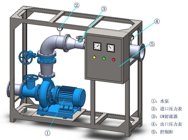
2. Selection of efficiency-increasing nozzles
The selection of efficiency nozzles is mainly determined from two aspects. First, determine the efficiency nozzle configuration method of a certain type of ejector unit through the "Attachment 3 Efficiency Nozzle Selection Table for Jet Units" (hereinafter referred to as Attachment 3), and make a preliminary selection of the efficiency nozzles; then screen the preliminary selection of efficiency nozzle configuration methods through the reasonable arrangement of the efficiency nozzles in the aeration tank.
A. When the width of the aeration tank is less than or equal to 6m
The service distance of the booster nozzle in the spray direction is 5m~6m. When the width of the aeration tank is less than or equal to 6m, arranging a row of efficiency nozzles in the direction of the tank width can meet the service distance in the spray direction.
In Example 1, the aeration tank type is 8m×5m×4m (water depth). The GW-T200B ejector unit is used to illustrate the selection of efficiency nozzles.
1) Preliminary selection by looking up the table: Find out from Appendix 3 that there are 6 methods for selecting and configuring the efficiency nozzle of the GW-T200B ejector unit, as follows:
① N70 efficiency nozzles: 4, nozzle spacing ≤3.5m
② N70B efficiency nozzles: 6, nozzle spacing ≤3m
③ N70C booster nozzles: 4 pcs, nozzle spacing ≤3m
④ N60 efficiency nozzles: 6, nozzle spacing ≤3m
⑤ N40 enhanced nozzles: 12, nozzle spacing ≤ 2.5m
⑥ N30 efficiency nozzles: 24, nozzle spacing ≤ 2.5m
2) Screen the preliminary selection through the reasonable arrangement of efficiency-enhancing nozzles
The pool width of this project is 5m, and the service distance in the spray direction of the synergistic nozzles is 5m to 6m, so a row of synergistic nozzles can be arranged in the direction of the pool width.
The pool length of this project is 8m, and the nozzle spacing for configuration methods ①~⑥ are: 8m/4 pieces=2m/piece, 8m/6 pieces=1.333m/piece, 8m/4 pieces=2m/piece, 8m/piece 6 pieces = 1.333m/piece, 8m/12 pieces = 0.667m/piece, 8m/24 pieces = 0.333m/piece, all within the nozzle spacing range required by each model of booster nozzle.
Therefore, from the perspective of layout, all configuration methods ① to ⑥ are feasible.
To sum up, there are 6 methods for selecting and configuring efficiency-enhancing nozzles for this project, as follows:
① N70 efficiency nozzles: 4, nozzle spacing ≤3.5m
② N70B efficiency nozzles: 6, nozzle spacing ≤3m
③ N70C booster nozzles: 4 pcs, nozzle spacing ≤3m
④ N60 efficiency nozzles: 6, nozzle spacing ≤3m
⑤ N40 enhanced nozzles: 12, nozzle spacing ≤ 2.5m
⑥ N30 efficiency nozzles: 24, nozzle spacing ≤ 2.5m
B. When the width of the aeration tank is greater than 6m
The service distance of the booster nozzles in the spray direction is 5m to 6m. When the width of the aeration tank is greater than 6m, arranging a row of booster nozzles in the direction of the tank width will not be able to meet the service distance parallel to the spray direction. Multiple rows of synergistic nozzles will be arranged in the direction of the pool width. The specific number of rows N=(pool width/5m).
Assuming that the aeration tank type is: 15m×9m×4m (water depth), the GW-T200B ejector unit is used to illustrate the selection and configuration of the efficiency nozzle.
The pool width of this project is 9m, which is greater than the service distance of 5m to 6m in the spray direction of the synergistic nozzles, so multiple rows of synergistic nozzles will be arranged in the direction of the pool width, and the specific number of rows is 2 rows (i.e. (pool width 9m/5m) rounded up.)
1) Preliminary selection by looking up the table: Find out from Appendix 3 that there are 6 methods for selecting and configuring the efficiency nozzle of the GW-T200B ejector unit, as follows:
① N70 efficiency nozzles: 4, nozzle spacing ≤3.5m
② N70B efficiency nozzles: 6, nozzle spacing ≤3m
③ N70C booster nozzles: 4 pcs, nozzle spacing ≤3m
④ N60 efficiency nozzles: 6, nozzle spacing ≤3m
⑤ N40 enhanced nozzles: 12, nozzle spacing ≤ 2.5m
⑥ N30 efficiency nozzles: 24, nozzle spacing ≤ 2.5m
2) Screen the preliminary selection through reasonable layout
The pool width of this project is 9m, and the service distance in the spray direction of the booster nozzles is 5m to 6m. Two rows of booster nozzles are arranged in the direction of the pool width; therefore, the number of nozzles is divided by 2 and arranged in the direction of the pool length.
The pool length of this project is 15m. The spacing between single row nozzles in the ①~⑥ configuration methods are: 15m/2=7.5m/piece, 15m/3=5m/piece, 15m/2=7.5m/piece, 15m/3=5m, 15 m/6 pieces = 2.5m/piece, 15m/12 pieces = 1.25m/piece, ①~④ selection and configuration are not within the required nozzle spacing range of each type of booster nozzle, ⑤, ⑥ selection and configuration methods are within the required nozzle spacing range.
To sum up, there are 5 methods for selecting and configuring the efficiency-enhancing nozzles for this project, as follows:
N40 booster nozzles, 12 pcs or N30 booster nozzles, 24 pcs.
3. Fan selection
A fan is not required for self-priming jet aeration, but it only needs to be used in conjunction with a fan for pressurized jet aeration. Directly check the air volume and air pressure of the fan under the corresponding water depth and ejector unit-blast and pressure model.
The project selection in Example 1 includes two options: self-priming and blowing and pressurizing. Self-priming does not require a fan, and only fan selection is required for blowing and pressurizing.
When the water depth is 4m, the fan parameters for blowing and pressurizing the GW-T200C jet unit are as follows:
Air volume: 6.72m³/min, wind pressure: 49kpa
The project selection in Example 2 also has two options: self-priming and blowing and pressurizing. Self-priming does not require a fan, and only fan selection is required for blowing and pressurizing.
When the water depth is 4m, the fan parameters for blowing and pressurizing the GW-T200D jet unit are as follows:
Air volume: 8.49m³/min, wind pressure: 49kpa.
The project selection in Example 3 also only selects the fan type for blower pressurization.
When the water depth is 4m, the fan parameters for blowing and pressurizing the GW-T200E jet unit are as follows:
Air volume: 10.18m³/min, wind pressure: 49kpa.
Attachment 1 Jet unit-self-priming series oxygenation capacity selection table
The oxygenation amount given in the table is the value under the conditions of water temperature 20℃, operating dissolved oxygen 2mg/L, salinity 0, coefficient θ=1.024; the other coefficients α, β, Ω and τ are 1.
| model | Oxygenation capacity at 4 m water depth (kg(O₂)/h) | Oxygenation volume at 5 m water depth (kg(O₂)/h) | Oxygenation capacity in 6 m water depth (kg(O₂)/h) | Oxygenation capacity at 7 m water depth (kg(O₂)/h) | Oxygenation capacity at 8 m water depth (kg(O₂)/h) | Oxygenation capacity in 9 m water depth (kg(O₂)/h) | Water power (kW) |
|---|---|---|---|---|---|---|---|
| GW-T300A | 12.47 | 13.06 | 13.65 | 14.25 | 14.48 | 15.43 | 7.45 |
| GW-T300B | 21.29 | 22.34 | 23.38 | 24.42 | 25.47 | 26.51 | 13.76 |
| GW-T300C | 32.22 | 33.86 | 35.51 | 37.15 | 38.80 | 40.44 | 20.79 |
| GW-T300D | 42.14 | 44.36 | 46.58 | 48.79 | 51.01 | 53.23 | 28.83 |
| GW-T300E | 54.85 | 57.86 | 60.88 | 63.89 | 66.91 | 69.92 | 37.84 |
| GW-T200A | 6.07 | 6.36 | 6.65 | 6.94 | 7.23 | 7.52 | 3.63 |
| GW-T200B | 10.20 | 10.70 | 11.20 | 11.70 | 12.20 | 12.70 | 6.59 |
| GW-T200C | 15.51 | 16.30 | 17.10 | 17.89 | 18.68 | 19.47 | 10.01 |
| GW-T200D | 20.31 | 21.44 | 22.51 | 23.58 | 24.66 | 25.73 | 13.93 |
| GW-T200E | 25.76 | 27.18 | 28.59 | 30.01 | 31.43 | 32.84 | 17.77 |
| GW-T150A | 3.84 | 4.02 | 4.20 | 4.38 | 4.57 | 4.75 | 2.29 |
| GW-T150B | 6.21 | 6.51 | 6.82 | 7.12 | 7.43 | 7.73 | 4.01 |
| GW-T150C | 9.55 | 10.03 | 10.52 | 11.01 | 11.49 | 11.98 | 6.16 |
| GW-T150D | 12.64 | 13.30 | 13.97 | 14.64 | 15.30 | 15.97 | 8.65 |
| GW-T150E | 16.62 | 17.53 | 18.45 | 19.36 | 20.27 | 21.19 | 11.47 |
| GW-T100A | 1.34 | 1.41 | 1.47 | 1.53 | 1.60 | 1.68 | 0.80 |
| GW-T100B | 2.31 | 2.42 | 2.53 | 2.65 | 2.76 | 2.87 | 1.49 |
| GW-T100C | 3.58 | 3.76 | 3.95 | 4.13 | 4.31 | 4.49 | 2.31 |
| GW-T100D | 4.71 | 4.95 | 5.20 | 5.45 | 5.70 | 5.94 | 3.22 |
| GW-T100E | 6.07 | 6.40 | 6.73 | 7.07 | 7.40 | 7.73 | 4.19 |
| GW-T80A | 0.77 | 0.80 | 0.84 | 0.88 | 0.91 | 0.95 | 0.46 |
| GW-T80B | 1.29 | 1.35 | 1.41 | 1.48 | 1.54 | 1.60 | 0.83 |
| GW-T80C | 1.97 | 2.07 | 2.17 | 2.27 | 2.37 | 2.47 | 1.27 |
| GW-T80D | 2.60 | 2.74 | 2.87 | 3.01 | 3.15 | 3.28 | 1.78 |
| GW-T80E | 3.41 | 3.59 | 3.78 | 3.97 | 4.16 | 4.34 | 2.35 |
| GW-T50A | 0.35 | 0.37 | 0.39 | 0.40 | 0.42 | 0.44 | 0.21 |
| GW-T50B | 0.58 | 0.60 | 0.63 | 0.66 | 0.69 | 0.72 | 0.37 |
| GW-T50C | 0.89 | 0.94 | 0.99 | 1.03 | 1.08 | 1.12 | 0.58 |
| GW-T50D | 1.19 | 1.26 | 1.32 | 1.38 | 1.45 | 1.51 | 0.82 |
| GW-T50E | 1.50 | 1.58 | 1.66 | 1.74 | 1.82 | 1.91 | 1.03 |
Note: The water power in Appendix 1 is the effective power of the water pump. When selecting a water pump, it needs to be divided by the motor efficiency to convert it into the water pump motor power.
Attachment 2 Jet unit-oxygenation capacity selection table for blast and pressurization series
The oxygenation amount given in the table is the value under the conditions of water temperature 20℃, operating dissolved oxygen 2mg/L, salinity 0, coefficient θ=1.024; the other coefficients α, β, Ω and τ are 1.
| Water depth (m) | 4 | 5 | 6 | 7 | 8 | 9 |
|---|---|---|---|---|---|---|
| Wind pressure (kPa) | 49 | 59 | 68 | 78 | 88 | 93 |
| model | parameter | 4 m water depth | 5 m water depth | 6 m water depth | 7 m water depth | 8 m water depth | 9 m water depth | Water power (kW) |
|---|---|---|---|---|---|---|---|---|
| GW-T300A | Oxygenation amount (kg(O₂)/h) | 28 | 34 | 42 | 52 | 59 | 65 | 7.45 |
| GW-T300A | Air volume (m³/min) | 5.68 | 6.47 | 7.22 | 8.10 | 9.04 | 9.53 | 7.45 |
| GW-T300B | Oxygenation amount (kg(O₂)/h) | 56 | 69 | 85 | 104 | 119 | 130 | 13.76 |
| GW-T300B | Air volume (m³/min) | 11.35 | 12.93 | 14.43 | 16.20 | 18.07 | 19.05 | 13.76 |
| GW-T300C | Oxygenation amount (kg(O₂)/h) | 70 | 86 | 105 | 129 | 148 | 162 | 20.79 |
| GW-T300C | Air volume (m³/min) | 14.13 | 16.09 | 17.96 | 20.16 | 22.49 | 23.70 | 20.79 |
| GW-T300D | Oxygenation amount (kg(O₂)/h) | 89 | 108 | 133 | 163 | 187 | 205 | 28.83 |
| GW-T300D | Air volume (m³/min) | 17.82 | 20.30 | 22.66 | 25.44 | 28.37 | 29.90 | 28.83 |
| GW-T300E | Oxygenation amount (kg(O₂)/h) | 106 | 130 | 159 | 195 | 224 | 245 | 37.84 |
| GW-T300E | Air volume (m³/min) | 21.39 | 24.35 | 27.19 | 30.52 | 34.05 | 35.88 | 37.84 |
| GW-T200A | Oxygenation amount (kg(O₂)/h) | 13.44 | 16.40 | 20.41 | 24.66 | 28.27 | 31.01 | 3.63 |
| GW-T200A | Air volume (m³/min) | 2.7 | 3.08 | 3.43 | 3.86 | 4.30 | 4.53 | 3.63 |
| GW-T200B | Oxygenation amount (kg(O₂)/h) | 26.89 | 36.90 | 40.29 | 49.34 | 56.57 | 62.04 | 6.59 |
| GW-T200B | Air volume (m³/min) | 5.41 | 6.16 | 6.87 | 7.72 | 8.61 | 9.07 | 6.59 |
| GW-T200C | Oxygenation amount (kg(O₂)/h) | 33.45 | 40.81 | 50.12 | 61.38 | 70.37 | 82.05 | 10.01 |
| GW-T200C | Air volume (m³/min) | 6.72 | 7.66 | 8.55 | 9.60 | 10.71 | 12.00 | 10.01 |
| GW-T200D | Oxygenation amount (kg(O₂)/h) | 42.21 | 51.50 | 63.24 | 77.45 | 88.80 | 97.38 | 13.93 |
| GW-T200D | Air volume (m³/min) | 8.49 | 9.66 | 10.79 | 12.11 | 13.51 | 14.28 | 13.93 |
| GW-T200E | Oxygenation amount (kg(O₂)/h) | 50.66 | 61.81 | 75.90 | 92.95 | 106.57 | 116.87 | 17.77 |
| GW-T200E | Air volume (m³/min) | 10.18 | 11.60 | 12.95 | 14.53 | 16.21 | 17.09 | 17.77 |
| GW-T150A | Oxygenation amount (kg(O₂)/h) | 8.48 | 10.35 | 12.71 | 17.84 | 17.84 | 19.57 | 2.29 |
| GW-T150A | Air volume (m³/min) | 1.71 | 1.94 | 2.17 | 2.43 | 2.71 | 2.86 | 2.29 |
| GW-T150B | Oxygenation amount (kg(O₂)/h) | 16.96 | 20.70 | 25.42 | 31.35 | 35.69 | 39.13 | 4.01 |
| GW-T150B | Air volume (m³/min) | 3.41 | 3.88 | 4.34 | 4.87 | 5.43 | 5.72 | 4.01 |
| GW-T150C | Oxygenation amount (kg(O₂)/h) | 21.10 | 25.75 | 31.62 | 38.73 | 44.40 | 48.69 | 6.16 |
| GW-T150C | Air volume (m³/min) | 4.24 | 4.83 | 5.39 | 6.05 | 6.75 | 7.12 | 6.16 |
| GW-T150D | Oxygenation amount (kg(O₂)/h) | 26.63 | 32.49 | 39.90 | 48.86 | 56.01 | 61.43 | 8.65 |
| GW-T150D | Air volume (m³/min) | 5.35 | 6.10 | 6.80 | 7.64 | 8.52 | 8.98 | 8.65 |
| GW-T150E | Oxygenation amount (kg(O₂)/h) | 31.96 | 38.99 | 47.89 | 58.64 | 67.24 | 73.73 | 11.47 |
| GW-T150E | Air volume (m³/min) | 6.42 | 7.32 | 8.17 | 9.17 | 10.23 | 10.78 | 11.47 |
| GW-T100A | Oxygenation amount (kg(O₂)/h) | 6.80 | 8.30 | 10.19 | 12.48 | 14.31 | 15.69 | 0.80 |
| GW-T100A | Air volume (m³/min) | 1.37 | 1.56 | 1.74 | 1.95 | 2.18 | 2.29 | 0.80 |
| GW-T100B | Oxygenation amount (kg(O₂)/h) | 10.08 | 12.29 | 15.10 | 18.49 | 21.20 | 23.25 | 1.49 |
| GW-T100B | Air volume (m³/min) | 2.03 | 2.31 | 2.58 | 2.89 | 3.22 | 3.40 | 1.49 |
| GW-T100C | Oxygenation amount (kg(O₂)/h) | 10.39 | 12.68 | 15.57 | 19.07 | 21.86 | 23.97 | 2.31 |
| GW-T100C | Air volume (m³/min) | 2.09 | 2.38 | 2.66 | 2.98 | 3.33 | 3.50 | 2.31 |
| GW-T100D | Oxygenation amount (kg(O₂)/h) | 11.00 | 13.42 | 16.48 | 20.18 | 23.14 | 25.37 | 3.22 |
| GW-T100D | Air volume (m³/min) | 2.21 | 2.52 | 2.81 | 3.16 | 3.52 | 3.71 | 3.22 |
| GW-T100E | Oxygenation amount (kg(O₂)/h) | 11.74 | 14.32 | 17.59 | 21.54 | 24.70 | 27.09 | 4.19 |
| GW-T100E | Air volume (m³/min) | 2.36 | 2.69 | 3.00 | 3.37 | 3.76 | 3.96 | 4.19 |
| GW-T80A | Oxygenation amount (kg(O₂)/h) | 3.31 | 4.04 | 4.96 | 6.08 | 6.97 | 7.64 | 0.46 |
| GW-T80A | Air volume (m³/min) | 0.67 | 0.76 | 0.85 | 0.95 | 1.06 | 1.12 | 0.46 |
| GW-T80B | Oxygenation amount (kg(O₂)/h) | 5.14 | 6.27 | 7.69 | 9.42 | 10.80 | 1.85 | 0.83 |
| GW-T80B | Air volume (m³/min) | 1.03 | 1.18 | 1.31 | 1.47 | 1.64 | 1.73 | 0.83 |
| GW-T80C | Oxygenation amount (kg(O₂)/h) | 5.93 | 7.24 | 8.89 | 10.88 | 12.48 | 13.68 | 1.27 |
| GW-T80C | Air volume (m³/min) | 1.19 | 1.36 | 1.52 | 1.70 | 1.90 | 2.00 | 1.27 |
| GW-T80D | Oxygenation amount (kg(O₂)/h) | 6.47 | 7.90 | 9.70 | 11.87 | 13.61 | 14.93 | 1.78 |
| GW-T80D | Air volume (m³/min) | 1.30 | 1.48 | 1.65 | 1.86 | 2.07 | 2.18 | 1.78 |
| GW-T80E | Oxygenation amount (kg(O₂)/h) | 7.17 | 8.74 | 10.74 | 13.15 | 15.08 | 16.54 | 2.35 |
| GW-T80E | Air volume (m³/min) | 1.44 | 1.64 | 1.83 | 2.06 | 2.29 | 2.43 | 2.35 |
| GW-T50A | Oxygenation amount (kg(O₂)/h) | 1.00 | 2.26 | 2.78 | 3.40 | 3.90 | 4.28 | 0.21 |
| GW-T50A | Air volume (m³/min) | 0.37 | 0.42 | 0.47 | 0.53 | 0.59 | 0.63 | 0.21 |
| GW-T50B | Oxygenation amount (kg(O₂)/h) | 2.40 | 2.93 | 3.59 | 4.40 | 5.05 | 5.53 | 0.37 |
| GW-T50B | Air volume (m³/min) | 0.48 | 0.55 | 0.61 | 0.69 | 0.77 | 0.81 | 0.37 |
| GW-T50C | Oxygenation amount (kg(O₂)/h) | 3.50 | 4.27 | 5.24 | 6.42 | 7.36 | 8.07 | 0.58 |
| GW-T50C | Air volume (m³/min) | 0.70 | 0.80 | 0.89 | 1.00 | 1.12 | 1.18 | 0.58 |
| GW-T50D | Oxygenation amount (kg(O₂)/h) | 3.88 | 4.73 | 5.81 | 7.12 | 8.16 | 8.95 | 0.82 |
| GW-T50D | Air volume (m³/min) | 0.78 | 0.89 | 0.99 | 1.11 | 1.24 | 1.31 | 0.82 |
| GW-T50E | Oxygenation amount (kg(O₂)/h) | 4.02 | 4.91 | 6.03 | 7.38 | 8.47 | 9.28 | 1.03 |
| GW-T50E | Air volume (m³/min) | 0.81 | 0.92 | 1.03 | 1.15 | 1.29 | 1.36 | 1.03 |
Note: The water power in Appendix 2 is the effective power of the water pump. When selecting a water pump, it needs to be divided by the motor efficiency to convert it into the motor power of the water pump.
Attachment 3 Ejector unit efficiency nozzle selection table
The service distance in the spray direction of all models of booster nozzles is 5m to 6m; see the table below for details of the spacing of booster nozzles.
| serial number | Enhanced nozzle model | Nozzle inlet nominal diameter (mm) | Nozzle spacing (m) | GW-T300A quantity (pieces) | GW-T300B quantity (pieces) | GW-T300C quantity (pieces) | GW-T300D quantity (pieces) | GW-T300E quantity (unit) |
|---|---|---|---|---|---|---|---|---|
| 1 | N70 | DN150 | ≤3.5 | 6 | 8 | 8 | 8 | 10 |
| 2 | N70B | DN150 | ≤3 | 8 | 10 | 10 | 12 | 12 |
| 3 | N70C | DN150 | ≤3 | 6 | 8 | 10 | 10 | 12 |
| 4 | N60 | DN150 | ≤3 | 8 | 10 | 12 | 12 | 14 |
| 5 | N40 | DN100 | ≤2.5 | 20 | 24 | 26 | 30 | 32 |
| serial number | Enhanced nozzle model | Nozzle inlet nominal diameter (mm) | Nozzle spacing (m) | GW-T200A quantity (pieces) | GW-T200B quantity (pieces) | GW-T200C quantity (pieces) | GW-T200D quantity (pieces) | GW-T200E quantity (unit) |
|---|---|---|---|---|---|---|---|---|
| 1 | N70 | DN150 | ≤3.5 | 3 | 4 | 4 | 4 | 4 |
| 2 | N70B | DN150 | ≤3 | 4 | 4 | 6 | 6 | 6 |
| 3 | N70C | DN150 | ≤3 | 4 | 4 | 4 | 6 | 6 |
| 4 | N60 | DN150 | ≤3 | 4 | 4 | 6 | 6 | 6 |
| 5 | N40 | DN100 | ≤2.5 | 8 | 12 | 12 | 14 | 14 |
| 6 | N30 | DN80 | ≤2.5 | 16 | 20 | 24 | 26 | 28 |
| serial number | Enhanced nozzle model | Nozzle inlet nominal diameter (mm) | Nozzle spacing (m) | GW-T150A quantity (pieces) | GW-T150B quantity (pieces) | GW-T150C quantity (pieces) | GW-T150D quantity (unit) | GW-T150E quantity (unit) |
|---|---|---|---|---|---|---|---|---|
| 1 | N40 | DN100 | ≤2.5 | 6 | 7 | 8 | 9 | 10 |
| 2 | N30 | DN80 | ≤2.5 | 10 | 12 | 14 | 16 | 18 |
| 3 | N20/N20B | DN50/DN65 | ≤1.5 | 16 | 18 | 20 | 22 | 24 |
| 4 | N20A/N20C | DN50/DN65 | ≤1 | 24 | 28 | 32 | 36 | 40 |
| serial number | Enhanced nozzle model | Nozzle inlet nominal diameter (mm) | Nozzle spacing (m) | GW-T100A quantity (pieces) | GW-T100B quantity (pieces) | GW-T100C quantity (pieces) | GW-T100D quantity (pieces) | GW-T100E quantity (unit) |
|---|---|---|---|---|---|---|---|---|
| 1 | N40 | DN100 | ≤2.5 | 2 | 3 | 3 | 3 | 3 |
| 2 | N30 | DN80 | ≤2.5 | 4 | 5 | 6 | 6 | 6 |
| 3 | N20/N20B | DN50/DN65 | ≤1.5 | 5 | 6 | 7 | 8 | 9 |
| 4 | N20A/N20C | DN50/DN65 | ≤1 | 8 | 10 | 12 | 14 | 14 |
| serial number | Enhanced nozzle model | Nozzle inlet nominal diameter (mm) | Nozzle spacing (m) | GW-T80A quantity (pieces) | GW-T80B quantity (pieces) | GW-T80C quantity (pieces) | GW-T80D quantity (pieces) | GW-T80E quantity (pieces) |
|---|---|---|---|---|---|---|---|---|
| 1 | N30 | DN80 | ≤2.5 | 2 | 3 | 3 | 3 | 4 |
| 2 | N20/N20B | DN50/DN65 | ≤1.5 | 3 | 4 | 4 | 5 | 5 |
| 3 | N20A/N20C | DN50/DN65 | ≤1 | 5 | 6 | 6 | 7 | 8 |
| serial number | Enhanced nozzle model | Nozzle inlet nominal diameter (mm) | Nozzle spacing (m) | GW-T50A quantity (pieces) | GW-T50B quantity (pieces) | GW-T50C quantity (pieces) | GW-T50D quantity (unit) | GW-T50E quantity (pieces) |
|---|---|---|---|---|---|---|---|---|
| 1 | N20 | DN50 | ≤1.5 | 1 | 2 | 2 | 2 | 2 |
| 2 | N20A | DN50 | ≤1 | 2 | 2 | 3 | 3 | 3 |
Appendix 4 Oxygenation correction calculation
AOTR=α×SOTR×θ/C*S20×(τ×Ω×β×C*S20-Cop)
CST=τ×Ω×β×C*S20
Among them, AOTR: oxygenation amount under actual operating conditions, kg/h.
SOTR: Oxygenation volume under standard conditions, kg/h. Standard conditions refer to water temperature of 20°C, atmospheric pressure of 1.013×10⁵Pa, and deoxygenated clean water.
AOTR(T=20℃,β=1): Oxygenation amount of jet aeration under given conditions, kg/h. The given conditions refer to the water temperature of 20℃, operating dissolved oxygen of 2mg/L, salinity of 0, coefficient θ=1.024; the remaining coefficients α, β, Ω and τ are 1.
C*S20: Under standard conditions (20℃, 1atm) saturated dissolved oxygen DO is equal to 9.08mg/L.
C*ST: Saturated dissolved oxygen DO under operating conditions, mg/L.
COP: Dissolved oxygen required for operation, generally 2mg/L.
τ:C*ST/C*S20
Ω: Correlation coefficient between saturated dissolved oxygen and operating pressure and standard pressure, Venturi ejector Ω=1.
β: The influence coefficient of sewage chemical properties on saturated dissolved oxygen; β=0.9~0.97.
α: Sewage KL/Clear water KL (Venturi jet α can reach 1, micropore aeration α is between 0.2 and 0.8).
θ: Operating temperature KL/standard temperature KL (usually experimental data indicates 1.024).
Oxygenation amount SOTR under standard conditions and actual oxygenation amount AOTR under given conditions of jet aeration(T=20℃,β=1)The relationship is as follows:
AOTR(T=20℃,β=1)=(α×SOTR×θ/C*S20)×(τ×Ω×β×C*S20-Cop)
=(1×SOTR×1.024/9.08)×(9.08-2)
=(1.024×SOTR/9.08)×7.08
When the operating conditions are different from the given conditions of the actual oxygenation amount of jet aeration, the actual oxygenation amount of jet aeration needs to be corrected. Among them: α and Ω take the value 1 in the Venturi jet and remain unchanged; θ takes the empirical constant 1.024; the dissolved oxygen concentration required for operation is 2 mg/L unchanged.
AOTR=(α×SOTR×θ/C*S20)×(τ×Ω×β×C*S20-Cop)
=(1×SOTR×1.024/9.08)×(β×C*ST-2)
=(1.024×SOTR/9.08)×(β×C*ST-2)
=AOTR(T=20℃,β=1)/7.08×(β×C*ST-2)
1. When the operating conditions are the same as those given in the table, the actual oxygenation amount is the look-up table value;
AOTR=AOTR(T=20℃,β=1)
2. When the operating conditions are different from the conditions given in the table, the actual oxygenation amount has the following relationship with the oxygenation amount value checked in the table:
AOTR=AOTR(T=20℃,β=1)/7.08×(β×C*ST-COP)
Among them: AOTR: actual oxygenation amount under operating conditions, kg/h;
AOTR(T=20℃,β=1): The actual oxygenation amount found in the table, kg/h; that is, the oxygenation amount under an actual condition where the water temperature is 20°C, the operating dissolved oxygen is 2mg/L, the salinity is 0, and the coefficient θ=1.024; the other coefficients α, β, Ω, and τ are 1;
β: The influence coefficient of sewage chemical properties on saturated dissolved oxygen; β=0.9~0.97;
C*ST: Saturated dissolved oxygen DO under operating conditions, mg/L;
COP: Dissolved oxygen required for operation, generally 2mg/L.
Appendix 5 Saturated dissolved oxygen concentration (mg/L) at different salinities and operating temperatures
| Water temperature (℃)/salinity (‰) | 0 | 5 | 10 | 15 | 20 | 25 | 30 | 35 | 40 | 45 |
|---|---|---|---|---|---|---|---|---|---|---|
| 15 | 10.07 | 9.77 | 9.47 | 9.19 | 8.91 | 8.64 | 8.38 | 8.13 | 7.88 | 7.65 |
| 18 | 9.45 | 9.17 | 8.9 | 8.64 | 8.39 | 8.14 | 7.9 | 7.66 | 7.44 | 7.22 |
| 20 | 9.08 | 8.81 | 8.56 | 8.31 | 8.07 | 7.83 | 7.6 | 7.38 | 7.17 | 6.96 |
| 22 | 8.73 | 8.48 | 8.23 | 8 | 7.77 | 7.54 | 7.33 | 7.12 | 6.91 | 6.72 |
| 25 | 8.24 | 8.01 | 7.79 | 7.57 | 7.36 | 7.15 | 6.95 | 6.75 | 6.56 | 6.38 |
| 28 | 7.81 | 7.59 | 7.38 | 7.18 | 6.98 | 6.79 | 6.61 | 6.423 | 6.25 | 6.08 |
| 30 | 7.54 | 7.33 | 7.14 | 6.94 | 6.75 | 6.57 | 6.39 | 6.22 | 6.05 | 5.89 |
| 35 | 6.93 | 6.75 | 6.58 | 6.4 | 6.24 | 6.07 | 5.92 | 5.76 | 5.61 | 5.46 |
| 38 | 6.61 | 6.44 | 6.28 | 6.12 | 5.96 | 5.81 | 5.66 | 5.51 | 5.37 | 5.24 |
Chengdu Green Water Technology Co., Ltd.
Address: Room 1408, AVIC City Plaza, No. 88, Middle Section of Fucheng Avenue, High-tech Zone, Chengdu Postal Code: 610041
Tel: 028-85130135 Fax: 028-85195416
E-mail:jane1984@cd-greenwater.com
Http://www.cd-greenwater.com
